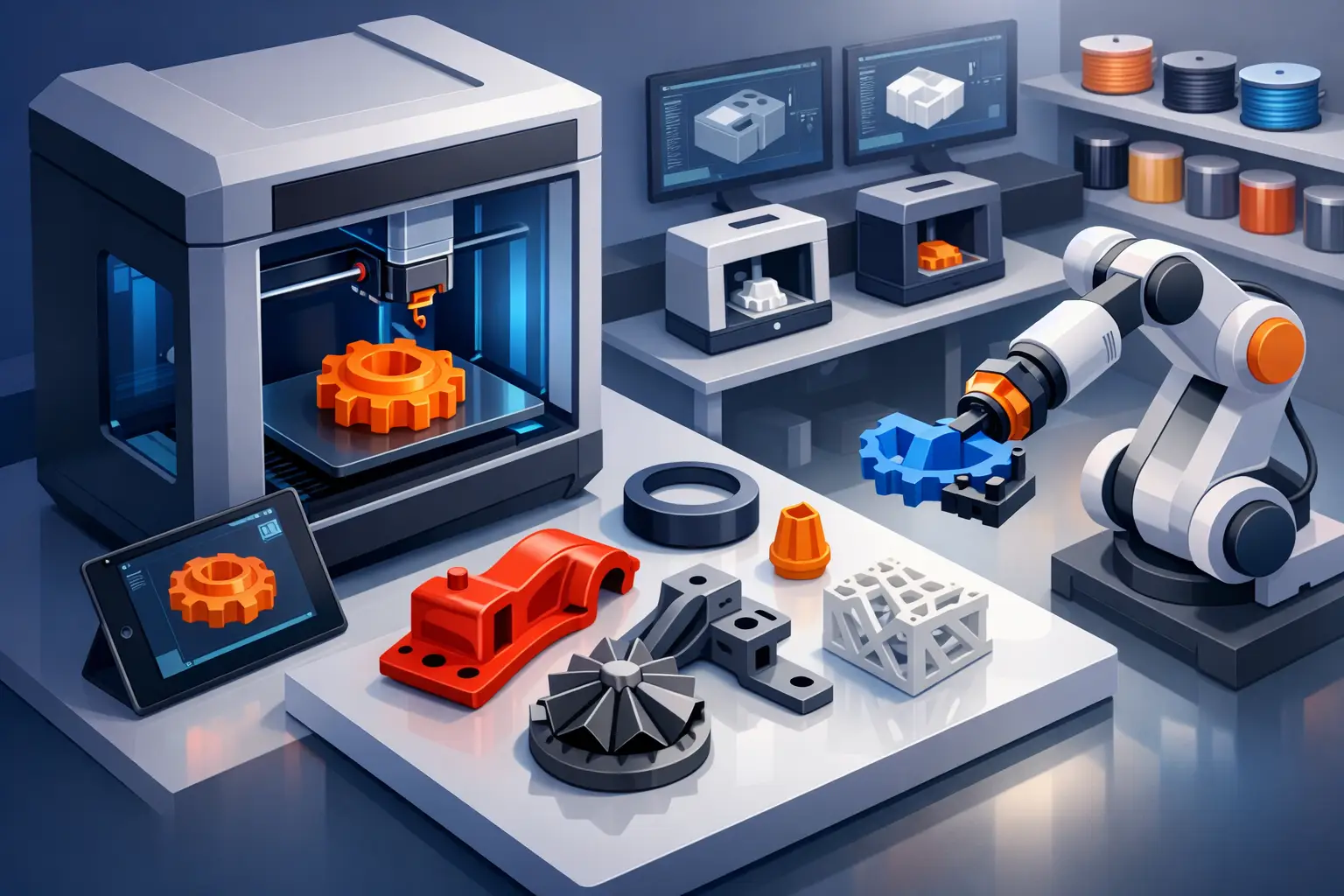
A printed part can look correct on screen and still fail at the production stage. Wall thickness may be too light for the selected process, a threaded feature may need machining, or the chosen material may not tolerate the intended load or temperature. Additive manufacturing works best when the digital model, functional requirement, material choice, production method, and fulfilment plan are treated as one controlled order.
For product teams, engineers, makers, and purchasing stakeholders, the value is not limited to producing a shape without conventional tooling. It is the ability to configure a part for a specific use, document the production requirements, and retain visibility from quotation through delivery.
What additive manufacturing is designed to do
Additive manufacturing produces a component by building it layer by layer from a digital file. Depending on the technology, those layers may be deposited as molten polymer, cured from resin, fused from powder, or formed through another controlled process. The method differs fundamentally from subtractive manufacturing, where material is removed from stock, and from moulding, where a tool is created before repeated parts are formed.
This approach is particularly useful when a project needs complex geometry, low-volume production, rapid iteration, replacement parts, jigs, fixtures, housings, enclosures, or design validation. Internal channels, lattice structures, consolidated assemblies, and geometry that would be expensive to machine can become practical production options.
That does not mean every part should be printed. For a high-volume item with stable geometry, injection moulding may provide a lower unit cost after tooling is justified. A machined part may be the better choice where very tight tolerances, surface finish, or a specific metal grade are central requirements. The useful question is not whether additive manufacturing can make the part. It is whether it is the appropriate process for the required quantity, performance, timeline, and budget.
Start with the part's job, not its appearance
A file upload is only one input to production. Before selecting a material or colour, define what the component must do. Is it a visual prototype, a fit-check model, a load-bearing bracket, a fixture used repeatedly on a shop floor, or a customer-facing end-use part? Those uses can require very different choices even when the geometry is identical.
A functional review should consider the forces applied to the part, its operating temperature, exposure to moisture or chemicals, required flexibility, expected service life, and the importance of dimensional accuracy. A cable guide, for example, may prioritize toughness and clean edges. A snap-fit enclosure may need controlled flexibility. A production fixture may require stiffness, heat resistance, and a finish that withstands repeated handling.
It also helps to identify the surfaces and features that matter most. Mating faces, holes, threads, bearing seats, sealing surfaces, and cosmetic faces often need different treatment than the rest of the model. Clearly noting those requirements at order stage reduces uncertainty later and helps determine whether post-processing or a secondary operation is needed.
Material selection is a performance decision
Material names alone do not define part performance. The same broad material family can behave differently depending on the printing technology, build orientation, layer settings, and post-processing. A practical material decision starts with the required property, then works back to the available production options.
For many early prototypes, standard polymers offer a cost-effective way to verify size, fit, assembly sequence, and user interaction. Engineering-focused polymers may be more appropriate where strength, impact resistance, thermal stability, or fatigue performance matter. Resin-based materials can provide fine detail and smooth surface characteristics, but their mechanical behaviour and long-term durability should be reviewed against the application. Metal processes may suit demanding mechanical or thermal uses, while introducing their own requirements for design, finishing, lead time, and cost.
Colour is also more than a visual preference. It can help distinguish revisions, indicate assembly positions, support demonstrations, or align a part with a product presentation. If colour consistency is critical, specify the requirement rather than assuming every process offers the same range or finish.
For repeat orders, record the selected material, colour, technology, and finishing method. That creates a usable production reference instead of relying on a previous file name or an informal description.
Build orientation affects the result
Layer-based production introduces directional behaviour. A part may be stronger in one direction than another, and its visible surface quality can vary according to how it is oriented during the build. Orientation also affects support structures, production time, warping risk, and the finish of critical faces.
A well-designed component accounts for this early. Where possible, avoid placing high-load features across weaker layer interfaces. Add fillets to reduce stress concentration, provide adequate wall thickness, and design holes or threaded features with downstream finishing in mind. These adjustments are often small, but they can prevent a reprint or make the difference between a prototype and a usable part.
Tolerances need a production plan
A CAD model may specify exact dimensions, but printed parts are produced within process-specific limits. Material shrinkage, thermal behaviour, layer formation, support removal, and finishing can all affect final dimensions. For this reason, tolerance requirements should be assigned to the features that genuinely need them rather than applied broadly without context.
If a part must slide onto a shaft, locate against another component, or accept a fastener, include the mating condition in the order notes. A clearance fit, press fit, or threaded connection may require an allowance in the model or a post-processing step after printing. When the assembly is new, a small test print can be the most efficient way to validate critical dimensions before producing a larger quantity.
This is especially relevant for teams moving from prototype to repeat production. The approved geometry is only part of the specification. The material, orientation considerations, finish, inspection expectations, and revision number should be managed alongside it.
Post-processing should be specified early
Many components are ready after basic support removal. Others need sanding, polishing, dyeing, painting, machining, tapping, inserts, vapour smoothing, or another finishing operation. Post-processing can improve appearance, fit, or function, but it also changes cost, lead time, and occasionally dimensions.
For example, a clean cosmetic surface may require a different orientation or additional finishing. A threaded hole may be more reliable with a heat-set insert or a tapped feature than with printed threads alone. A part used in a controlled business process may require certification or documented checks. These are not last-minute add-ons. They are production inputs that should be established with the material and technology selection.
When an order includes several parts, distinguish between items that need enhanced finishing and those that only need functional utility. Applying the same finish to every item can add cost without improving the outcome.
Order control matters as much as print capability
For a one-off model, informal communication may be enough. For repeat orders, shared projects, or purchasing workflows, controlled order information becomes essential. Teams need a clear record of the file revision, selected options, charges, invoices, payment status, delivery details, and current production stage.
A centralized ordering process prevents common errors: an earlier revision being printed, a different material being assumed, a finish being omitted, or a shipment being sent to an outdated address. It also gives non-technical stakeholders a way to review order status without needing access to production equipment or design software.
Print3Dcanada is structured around that lifecycle, allowing users to configure production details, manage orders, and track progress through fulfilment. This is useful when the print itself is only one task in a broader design, procurement, or operations process.
Prepare files for fewer production delays
A production-ready file should be a closed, watertight model with no unintended internal geometry, reversed normals, or overlapping bodies. Export format matters as well. STL remains common for many workflows, while formats that retain units, colour, or richer geometry data may be preferable where supported.
Before submitting, check the model at its intended scale and confirm that thin walls, small text, pins, clips, and unsupported overhangs suit the selected process. Remove geometry that is not meant to print, such as construction bodies or duplicate parts. If the design contains an assembly, confirm whether it should be printed as separate components or as one consolidated piece.
Name files and order line items in a way that supports traceability. A label that includes the part identifier and revision is more useful than a generic filename. Where a change affects fit or material performance, issue a new revision rather than overwriting the prior production reference.
Plan the first order as a baseline
The first production order should establish more than whether the part can be printed. It should confirm the material selection, dimensions at critical interfaces, surface expectations, finishing needs, packaging requirements, and delivery timing. Capture what worked and what changed.
That baseline makes later ordering faster and more dependable, whether you need one replacement component or a controlled batch for a team. Specify the part's job clearly, keep the production record attached to the order, and let the next decision be based on measured results rather than assumptions.