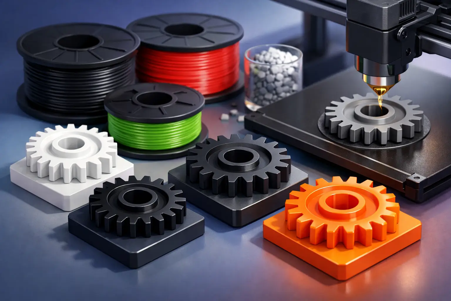
A gear that prints cleanly can still fail after a few operating cycles. Tooth wear, heat buildup, poor layer orientation, shaft fit, and insufficient backlash can matter more than surface appearance. The best 3d printing material for gears therefore depends on the gear’s duty cycle, mating part, operating temperature, load, lubrication, and required service life.
For a low-load prototype, a commonly available engineering plastic may be sufficient. For a production fixture, drive mechanism, or repeated-motion assembly, material selection needs to account for friction and dimensional stability alongside tensile strength. Start with the application, then select the material and printing process that can consistently produce the required geometry.
What a 3D-printed gear needs to do
Gears experience a combination of contact stress, bending at the tooth root, friction, and heat. A material may be strong in a static test but perform poorly as gear teeth repeatedly slide and roll against a mating component. The right choice must resist wear, retain its shape under load, and tolerate the temperature created by the assembly.
Dimensional accuracy is equally relevant. Gear tooth profiles require controlled pitch diameter, bore size, concentricity, and backlash. A small dimensional error can create noise, binding, uneven tooth contact, or accelerated wear. Material shrinkage and moisture absorption should be considered before finalizing tolerances.
Layer direction also affects performance in filament-based printing. Teeth loaded across weak layer bonds may split at the root even when the selected polymer is otherwise suitable. Printing orientation, wall count, infill strategy, and post-processing are production inputs, not finishing details.
Best 3D printing material for gears by application
Nylon is usually the leading choice for functional polymer gears
Nylon, including PA12 and other polyamide grades, is often the strongest starting point for functional 3D-printed gears. It offers good toughness, fatigue resistance, and wear performance relative to standard printing plastics. Its low-friction behaviour also makes it better suited to repeated tooth contact than brittle materials.
Nylon is particularly useful for moderate-load gears, housings with integrated gearing, robotics components, jigs with moving mechanisms, and prototype assemblies that need to run rather than simply demonstrate form. Reinforced nylon can increase stiffness and reduce deformation, but fibre-filled grades may be more abrasive to mating surfaces and can reduce impact resistance. They are not automatically the best option for every gear pair.
The main trade-off is moisture. Nylon absorbs humidity, which can alter dimensions and mechanical behaviour. For close-tolerance gears, material conditioning, storage, and the expected operating environment should be specified as part of the order requirement. Select a process and material grade appropriate for the target tolerance rather than relying on nominal dimensions alone.
Acetal is a strong option where low friction matters most
Acetal, commonly known as POM, is widely used in conventionally manufactured gears because it has low friction, good wear resistance, and good dimensional stability. Where an additive manufacturing process supports it reliably, acetal can be an excellent choice for gears that need smooth movement and reduced moisture sensitivity.
It is well suited to small mechanical assemblies, light-to-medium duty gear trains, and components requiring a stable bore or tooth profile. However, acetal is more demanding to print than common filaments. Warping, adhesion, and process control can affect results. Its availability may also be more limited than nylon or PETG, especially when a specific production technology is required.
Use acetal when its performance advantages are needed and the selected manufacturing process can control the part consistently. It is a material decision that should be matched to validated machine capability, not a default assumption based on conventional machining applications.
PETG works for light-duty prototypes and simple mechanisms
PETG is accessible, tough enough for many non-critical applications, and generally easier to print than nylon or acetal. It can be appropriate for display mechanisms, low-load hand-operated gears, educational models, and early fit-and-function prototypes.
Its limitations appear under sustained load and friction. PETG can creep, soften at elevated temperatures, and wear more quickly than engineering polymers in a continuously running gear train. It is a practical choice when speed, cost control, and basic functional validation are the primary requirements, but it should not be specified for demanding power transmission without testing.
PETG is often useful during the first iteration because it can reveal clearance, centre-distance, and housing-fit issues before a higher-performance material is ordered.
ABS and ASA suit enclosed or moderate-temperature assemblies
ABS and ASA provide better heat resistance than PETG and can work for moderate-duty gears where environmental exposure or temperature is a concern. ASA adds improved weather resistance, making it relevant for external enclosures and mechanisms exposed to sunlight.
Neither material generally matches nylon or acetal for wear performance. They are better considered when temperature stability, cost, and printability are more important than long-term gear contact performance. For intermittent mechanisms, actuator covers, or lightly loaded gearing inside a broader printed assembly, they can be effective.
Metal is for high-load, high-temperature, or long-life requirements
Metal additive manufacturing may be appropriate when a gear must carry high torque, withstand heat, maintain tooth geometry over a long service life, or meet a defined engineering specification. Stainless steel, tool steel, aluminium, and other alloys each introduce different strength, weight, corrosion, and finishing considerations.
A metal-printed gear is not necessarily ready for use directly from the build. Critical gear surfaces may require machining, honing, heat treatment, or other post-processing to reach the required tooth accuracy and surface finish. These additional steps affect cost and lead time, but they may be necessary for a part that must perform in a demanding assembly.
For many applications, a hybrid design is more efficient: use a standard metal gear for the wear surface and 3D print the carrier, housing, fixture, or low-load driven component.
Material choice is only one part of gear performance
Before selecting a material, define whether the gear is a proof-of-concept part, a low-volume end-use component, or a production aid. The same CAD file may require different materials at each stage. A visual prototype can prioritize speed and price, while an operating component needs a defined load case and test plan.
Specify the mating gear material as well. A nylon gear running against metal behaves differently from two printed polymer gears in contact. Two fibre-filled gears may create excessive abrasion. A softer polymer gear can be deliberately selected as the sacrificial component if it is easier and less expensive to replace than the mating part.
Lubrication can improve wear life, but it also changes the material requirements. Confirm chemical compatibility between the lubricant and the polymer. Some assemblies should run dry, particularly where contamination control is required, which increases the value of naturally low-friction materials such as nylon or acetal.
Design and production checks before ordering
A successful gear order begins with complete operating information. Include the module or diametral pitch, pressure angle, tooth count, face width, bore requirements, keyways or set-screw features, mating gear details, target torque, speed, duty cycle, and operating temperature. If the gear is part of a larger assembly, provide the centre distance and acceptable backlash range.
Avoid designing the bore at an exact nominal shaft diameter without considering the selected process. Printed holes may need an allowance, reaming operation, insert, or post-machining step to achieve the required fit. For a gear transmitting torque through a shaft, a plain press fit may not be sufficient. A keyed hub, splines, clamping feature, or metal insert can provide a more reliable load path.
Ask for a production approach that identifies material, colour where relevant, printing technology, post-processing, and delivery requirements in the same order record. This is especially helpful for repeat gear sets, where traceable specifications prevent an approved part from being unintentionally reordered in a different material or process.
Make the first gear a controlled test part
For most functional gear projects, nylon is the most practical first material to evaluate. Choose acetal when low friction and dimensional stability are the priority and the process supports it. Use PETG, ABS, or ASA for lower-duty prototypes where their specific advantages fit the environment. Move to metal, machining, or a hybrid solution when load, temperature, precision, or service-life requirements exceed what printed polymers can reliably support.
The most useful next step is to order a test gear with the intended mating component and operating conditions in mind. Measure backlash, inspect tooth contact, run the planned duty cycle, and record the material and process settings that pass. That record turns a one-off print into a repeatable production specification.