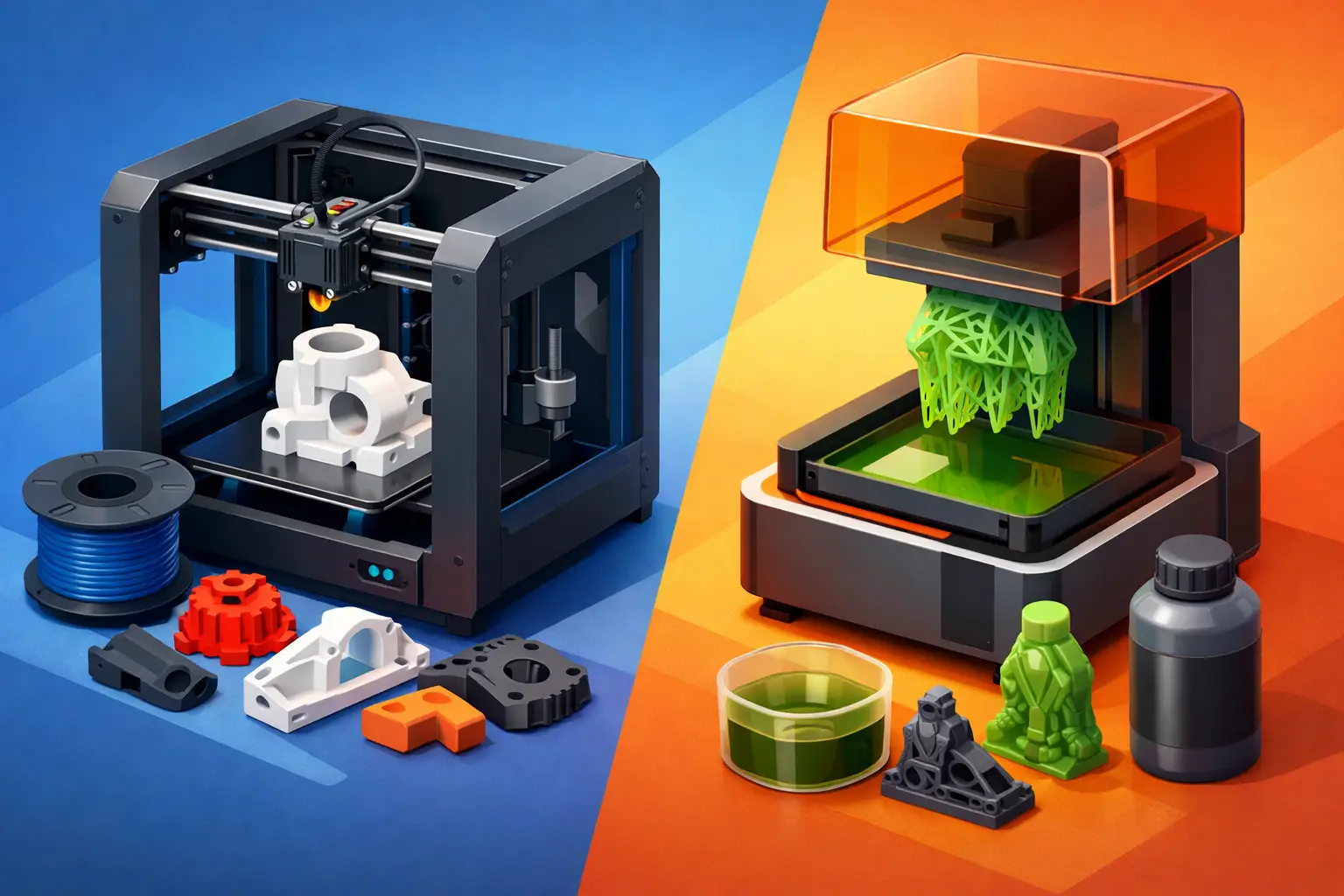
A small enclosure can look correct in a CAD file and still fail its intended use if the printing process is wrong. In FDM versus SLA printing, the decision is not simply about surface appearance. It affects dimensional requirements, material behaviour, post-processing, part orientation, unit cost, and whether the result is suitable for a prototype, fixture, display model, or end-use component.
For custom part orders, start with the function of the part. A fine-detail concept model and a load-bearing bracket may share similar dimensions, but they place very different demands on the printing process.
FDM versus SLA Printing: The Core Difference
FDM, or fused deposition modelling, creates a part by extruding melted thermoplastic through a nozzle, layer by layer. Common FDM materials include PLA, PETG, ABS, ASA, TPU, and nylon. The process is widely used for functional prototypes, jigs, fixtures, housings, and larger components where material performance and cost control matter.
SLA, or stereolithography, creates a part by curing liquid resin with a controlled light source. It can produce very fine layers and smooth surfaces, making it well suited to detailed visual models, intricate features, dental or jewellery patterns, miniatures, and prototypes where appearance or small geometry is central to the requirement.
Both processes build parts in layers, but the materials and manufacturing constraints are different. FDM parts are thermoplastic components with visible layer lines and directional strength. SLA parts are resin components with high detail capability, but their material behaviour and post-processing requirements must be considered carefully.
Surface Finish and Feature Detail
SLA is generally the stronger option when a part needs a smooth surface directly from the printer. Fine text, shallow embossing, small holes, miniature features, and organic shapes can reproduce with more definition than a typical FDM print. Layer lines are still present, but they are often much less visible.
FDM can produce clean functional parts, particularly when geometry is designed for the process and an appropriate layer height is selected. However, the extrusion path remains visible on curved or angled surfaces. This is not necessarily a defect. For brackets, machine guards, workshop aids, and internal assemblies, visible layers may be fully acceptable.
The required finish should be specified early because post-processing changes cost and lead time. Sanding, priming, painting, vapour smoothing, polishing, and other finishing steps may improve appearance, but they do not replace choosing the correct production method. If a polished visual prototype is required, SLA may reduce the amount of finishing needed. If the part will be painted or hidden inside an assembly, FDM may be the more practical starting point.
Strength Depends on Material and Load Direction
FDM is often selected for functional use because it supports a broad range of engineering-oriented thermoplastics. PETG can offer a useful balance of durability and chemical resistance. ASA is often considered for outdoor exposure. TPU provides flexibility. Nylon can suit applications that need toughness and wear resistance.
However, FDM strength is directional. A printed part is usually strongest within each deposited layer and more vulnerable across layer boundaries. Part orientation therefore matters. A hook printed flat may perform differently from the same hook printed upright, even when the material and dimensions are unchanged. When ordering a functional part, identify the expected load, fastener locations, impact risk, heat exposure, and the direction of force.
Standard SLA resins are often more rigid and can be more brittle than common FDM thermoplastics. They can be appropriate for detailed prototypes and presentation components, but they should not automatically be treated as substitutes for engineering plastics. Specialty tough, flexible, high-temperature, or durable resins can expand the range of SLA applications, although they still require selection based on the actual use case.
For a part that will flex repeatedly, carry weight, receive threaded fasteners, or operate outdoors, material data and geometry should guide the choice more than visual quality alone.
Dimensional Accuracy and Tolerances
SLA can deliver excellent dimensional detail, especially on small components, but no additive process should be treated as zero-tolerance manufacturing. Resin curing, support placement, washing, and post-curing can influence final dimensions. Thin walls and long unsupported shapes may also distort.
FDM tolerances are influenced by nozzle diameter, layer height, material shrinkage, cooling, machine calibration, and orientation. Large flat surfaces may lift or warp with some materials. Holes printed horizontally can require allowance, while mating components may need clearance designed into the model.
A useful approach is to identify critical dimensions instead of applying tight tolerances to every feature. Call out interfaces such as bearing seats, snap fits, shaft holes, gasket channels, fastener holes, and assemblies with purchased components. If a feature must fit another part, state the required clearance and intended function. This gives the production team a clearer basis for selecting technology, orientation, and any required finishing steps.
Neither FDM nor SLA is automatically better for every precision part. SLA is frequently preferred for small detailed geometry. FDM can be very effective for larger functional components when tolerance expectations match the process and material.
Supports, Orientation, and Part Design
Both processes may require supports, but the consequences are different. FDM supports are printed from the same material or, in some cases, a separate support material. They can leave witness marks where they contact the part, especially on downward-facing surfaces. Overhangs, bridges, enclosed cavities, and internal channels should be reviewed before production.
SLA parts are commonly built at an angle and supported at multiple points. This helps manage peel forces during printing and can improve reliability, but support contact points require removal and finishing. The most visible face of a display part should generally be positioned to minimize support marks.
For either process, avoid treating the original CAD orientation as the final print orientation. A production-oriented review may identify opportunities to reduce supports, improve strength, protect cosmetic surfaces, or lower cost. Features such as thin pins, knife edges, unsupported walls, deep narrow cavities, and trapped resin volumes need particular attention in SLA designs.
Cost and Lead Time Are Not the Same Question
FDM is often more economical for larger parts, simple geometries, and functional prototypes. Material costs can be lower, and many parts require limited post-processing. Print time can still increase significantly with high infill, fine layers, thick walls, or extensive supports.
SLA may be cost-effective for small, highly detailed parts, particularly when finish quality prevents additional labour later in the workflow. Yet resin handling, washing, support removal, and post-curing are part of the process. A part that looks quick to print may still require careful finishing before it is ready for inspection or use.
Lead time should be evaluated as a complete order requirement: material availability, machine capacity, printing duration, post-processing, quality checks, shipping, and delivery. For repeat orders, keeping the same approved material, colour, orientation, and finishing specification helps maintain consistency and reduces avoidable clarification.
Choosing the Right Process for the Part
Choose FDM when the part needs a practical thermoplastic, larger dimensions, cost-efficient production, or functional characteristics such as toughness, flexibility, weather resistance, or heat performance. It is often the appropriate route for workshop tools, housings, mounting hardware, manufacturing aids, and iterative engineering prototypes.
Choose SLA when fine detail, smooth finish, small feature definition, or presentation quality is the primary requirement. It is commonly a strong choice for visual prototypes, detailed models, form studies, intricate components, and patterns that benefit from accurate surface reproduction.
There are cases where both methods are valid. A product team may use SLA for an early design review model, then move to FDM for fit testing and functional evaluation. A small manufacturer may use FDM for a durable jig while using SLA for a detailed customer sample. The correct answer can change as the project moves from concept to validation to production support.
Before submitting a job, record the part’s intended use, required material properties, critical dimensions, colour, quantity, finish expectation, and delivery deadline. A structured order workflow makes those requirements visible from material selection through production and fulfilment. Print3Dcanada customers can use that information to configure a clearer request and track the job as it progresses.
The most useful printing choice is the one that reduces risk at the next stage of your project. Specify the functional requirement first, then select FDM or SLA based on what the part must do after it leaves the printer.